ANSI, ASME, ASA, B16.5 WELDING NECK FLANGE
CLASS 150 / 300 / 600 FLANGE
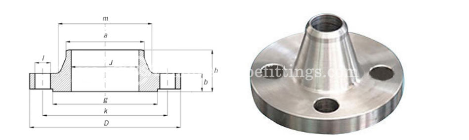
Flange Dimensions & Approximate Masses / Flange Weight
|
Table ANSI, ASME, ASA, B16.5 150lb/sq.in. WELDING NECK FLANGE RF |
|||||||||||
|
ø |
D |
b |
g |
m |
a |
J* |
h |
k |
Holes |
l |
Kg. |
|
1/2″ |
88,9 |
11,1 |
34,9 |
30,2 |
21,3 |
15,7 |
47,6 |
60,3 |
4 |
15,9 |
0,500 |
|
3/4″ |
98,4 |
12,7 |
42,9 |
38,1 |
26,7 |
20,8 |
52,4 |
69,8 |
4 |
15,9 |
0,700 |
|
1″ |
107,9 |
14,3 |
50,8 |
49,2 |
33,5 |
26,7 |
55,6 |
79,4 |
4 |
15,9 |
1,100 |
|
1 1/4″ |
117,5 |
15,9 |
63,5 |
58,8 |
42,2 |
35,1 |
57,1 |
88,9 |
4 |
15,9 |
1,500 |
|
1 1/2″ |
127,0 |
17,5 |
73,0 |
65,1 |
48,3 |
40,9 |
61,9 |
98,4 |
4 |
15,9 |
1,800 |
|
2″ |
152,4 |
19,0 |
92,1 |
77,8 |
60,3 |
52,6 |
63,5 |
120,6 |
4 |
19,0 |
2,700 |
|
2 1/2″ |
177,8 |
22,2 |
104,8 |
90,5 |
73,1 |
62,7 |
69,8 |
139,7 |
4 |
19,0 |
4,400 |
|
3″ |
190,5 |
23,8 |
127,0 |
107,9 |
88,9 |
78,0 |
69,8 |
152,4 |
4 |
19,0 |
5,200 |
|
3 1/2″ |
215,9 |
23,8 |
139,7 |
122,2 |
101,6 |
90,2 |
71,4 |
177,8 |
8 |
19,0 |
6,400 |
|
4″ |
228,6 |
23,8 |
157,2 |
134,9 |
114,3 |
102,4 |
76,2 |
190,5 |
8 |
19,0 |
7,500 |
|
5″ |
254,0 |
23,8 |
185,7 |
163,5 |
141,2 |
128,3 |
88,9 |
215,9 |
8 |
22,2 |
9,200 |
|
6″ |
279,4 |
25,4 |
215,9 |
192,1 |
168,4 |
154,2 |
88,9 |
241,3 |
8 |
22,2 |
11,000 |
|
8″ |
342,9 |
28,6 |
269,9 |
246,1 |
219,1 |
202,7 |
101,6 |
298,4 |
8 |
22,2 |
18,300 |
|
10″ |
406,4 |
30,2 |
323,8 |
304,8 |
273,0 |
254,5 |
101,6 |
361,9 |
12 |
25,4 |
25,000 |
|
12″ |
482,6 |
31,7 |
381,0 |
365,1 |
323,8 |
304,8 |
114,3 |
431,8 |
12 |
25,4 |
39,000 |
|
14″ |
533,4 |
34,9 |
412,7 |
400,0 |
355,6 |
336,5 |
127,0 |
476,2 |
12 |
28,6 |
51,000 |
|
16″ |
596,9 |
36,5 |
469,9 |
457,2 |
406,4 |
387,3 |
127,0 |
539,7 |
16 |
28,6 |
60,000 |
|
18″ |
635,0 |
39,7 |
533,4 |
504,8 |
457,2 |
438,1 |
139,7 |
577,8 |
16 |
31,7 |
71,000 |
|
20″ |
698,5 |
42,9 |
584,2 |
558,8 |
508,0 |
488,9 |
144,5 |
635,0 |
20 |
31,7 |
88,000 |
|
22″ |
749,3 |
46,0 |
641,2 |
609,6 |
558,8 |
539,7 |
149,2 |
692,1 |
20 |
34,9 |
102,000 |
|
24″ |
812,8 |
47,6 |
692,1 |
663,6 |
609,6 |
590,5 |
152,4 |
749,3 |
20 |
34,9 |
119,000 |
|
* |
The data “J” corresponds to the STD schedule | ||||||||||
NOTE:
1. Class 150 flanges except Lap Joint will be furnished with 0.06 (1.6mm) raised face, which is included in ‘Thickness’ (C) and ‘Length through Hub’ (Y1), (Y3).
2. For Slip-on, Threaded, Socket Welding and Lap Joint Flanges, the hubs can be shaped either vertical from base to top or tapered within the limits of 7 degrees.
3. Blind Flanges may be made with the same hub as that used for Slip-on Flanges or without hub.
4. The gasket surface and backside (bearing surface for bolting) are made parallel within 1 degree. To accomplish parallelism, spot facing is carried out according to MSS SP-9, without reducing thickness (C).
5. Depth of Socket (D) is covered by ANSI B 16.5 only in sizes through 3 inch, over 3 inch is at the manufacturer’s option.
6. Welding Neck Flange Bore Size SCH10, SCH20, SCH30, STD, SCH40, SCH60, SCH80, SCH100, SCH 120, SCH140, SCH160, XS
|
Table ANSI, ASME, ASA B16.5 300lb/sq.in. WELDING NECK FLANGE RF |
|||||||||||
|
ø |
D |
b |
g |
m |
a |
J* |
h |
k |
Holes |
l |
Kg. |
|
1/2″ |
95,2 |
14,3 |
34,9 |
38,1 |
21,3 |
15,7 |
52,4 |
66,7 |
4 |
15,9 |
0,900 |
|
3/4″ |
117,5 |
15,9 |
42,9 |
47,6 |
26,7 |
20,8 |
57,1 |
82,5 |
4 |
19,0 |
1,500 |
|
1″ |
123,8 |
17,5 |
50,8 |
54,0 |
33,5 |
26,7 |
61,9 |
88,9 |
4 |
19,0 |
1,900 |
|
1 1/4″ |
133,3 |
19,0 |
63,5 |
63,5 |
42,2 |
35,1 |
65,1 |
98,4 |
4 |
19,0 |
2,600 |
|
1 1/2″ |
155,6 |
20,6 |
73,0 |
69,8 |
48,3 |
40,9 |
68,3 |
114,3 |
4 |
22,2 |
3,300 |
|
2″ |
165,1 |
22,2 |
92,1 |
84,1 |
60,3 |
52,6 |
69,8 |
127,0 |
8 |
19,0 |
3,600 |
|
2 1/2″ |
190,5 |
25,4 |
104,8 |
100,0 |
73,1 |
62,7 |
76,2 |
149,2 |
8 |
22,2 |
5,400 |
|
3″ |
209,5 |
28,6 |
127,0 |
117,5 |
88,9 |
78,0 |
79,4 |
168,3 |
8 |
22,2 |
7,400 |
|
3 1/2″ |
228,6 |
30,2 |
139,7 |
133,3 |
101,6 |
90,2 |
81,0 |
184,1 |
8 |
22,2 |
8,900 |
|
4″ |
254,0 |
31,7 |
157,2 |
146,0 |
114,3 |
102,4 |
85,7 |
200,0 |
8 |
22,2 |
11,900 |
|
5″ |
279,4 |
34,9 |
185,7 |
177,8 |
141,2 |
128,3 |
98,4 |
234,9 |
8 |
22,2 |
16,000 |
|
6″ |
317,5 |
36,5 |
215,9 |
206,4 |
168,4 |
154,2 |
98,4 |
269,9 |
12 |
22,2 |
20,200 |
|
8″ |
381,0 |
41,3 |
269,9 |
260,3 |
219,1 |
202,7 |
111,1 |
330,2 |
12 |
25,4 |
31,000 |
|
10″ |
444,5 |
47,6 |
323,4 |
320,7 |
273,0 |
254,5 |
117,5 |
387,3 |
16 |
28,6 |
44,300 |
|
12″ |
520,7 |
50,8 |
381,0 |
374,6 |
323,8 |
304,8 |
130,2 |
450,8 |
16 |
31,7 |
64,000 |
|
14″ |
584,2 |
54,0 |
412,7 |
425,4 |
355,6 |
336,5 |
142,9 |
514,3 |
20 |
31,7 |
88,000 |
|
16″ |
647,7 |
57,1 |
469,9 |
482,6 |
406,4 |
387,3 |
146,0 |
571,5 |
20 |
34,9 |
113,000 |
|
18″ |
711,2 |
60,3 |
533,4 |
533,4 |
457,2 |
438,1 |
158,7 |
628,6 |
24 |
34,9 |
134,000 |
|
20″ |
774,7 |
63,5 |
584,2 |
587,4 |
508,0 |
488,9 |
161,9 |
685,8 |
24 |
34,9 |
171,000 |
|
22″ |
838,2 |
66,7 |
641,2 |
641,2 |
558,8 |
539,7 |
165,1 |
742,9 |
24 |
41,3 |
195,000 |
|
24″ |
914,4 |
69,8 |
692,1 |
701,7 |
609,6 |
590,5 |
168,3 |
812,8 |
24 |
41,3 |
238,000 |
|
* |
The data “J” corresponds to the STD schedule | ||||||||||
NOTE:
1. Class 300 flanges except Lap Joint will be furnished with 0.06 (1.6mm) raised face, which is included in ‘Thickness’ (C) and ‘Length through Hub’ (Y1), (Y3).
2. For Slip-on, Threaded, Socket Welding and Lap Joint Flanges, the hubs can be shaped either vertical from base to top or tapered within the limits of 7 degrees.
3. Blind Flanges may be made with the same hub as that used for Slip-on Flanges or without hub.
4. The gasket surface and backside (bearing surface for bolting) are made parallel within 1 degree. To accomplish parallelism, spot facing is carried out according to MSS SP-9, without reducing thickness (C).
5. Depth of Socket (D) is covered by ANSI B 16.5 only in sizes through 3 inch, over 3 inch is at the manufacturer’s option.
6. Welding Neck Flange Bore Size SCH10, SCH20, SCH30, STD, SCH40, SCH60, SCH80, SCH100, SCH 120, SCH140, SCH160, XS
|
Table ANSI/ASME/ASA B16.5 600lb/sq.in. WELDING NECK FLANGE RF |
|||||||||||
|
ø |
D |
b |
g |
m |
a |
J* |
h |
k |
Holes |
l |
Kg. |
|
1/2″ |
95,2 |
14,3 |
34,9 |
38,1 |
21,3 |
15,7 |
52,4 |
66,7 |
4 |
15,9 |
0,900 |
|
3/4″ |
117,5 |
15,9 |
42,9 |
47,6 |
26,7 |
20,9 |
57,1 |
82,5 |
4 |
19,0 |
1,500 |
|
1″ |
123,8 |
17,5 |
50,8 |
54,0 |
33,5 |
26,7 |
61,9 |
88,9 |
4 |
19,0 |
1,900 |
|
1 1/4″ |
133,3 |
20,6 |
63,5 |
63,5 |
42,2 |
35,0 |
66,7 |
98,4 |
4 |
19,0 |
2,600 |
|
1 1/2″ |
155,6 |
22,2 |
73,0 |
69,8 |
48,3 |
40,9 |
69,8 |
114,3 |
4 |
22,2 |
3,300 |
|
2″ |
165,1 |
25,4 |
92,1 |
84,1 |
60,3 |
52,6 |
73,0 |
127,0 |
8 |
19,0 |
4,700 |
|
2 1/2″ |
190,5 |
28,6 |
104,8 |
100,0 |
73,1 |
62,7 |
79,4 |
149,2 |
8 |
22,2 |
6,500 |
|
3″ |
209,5 |
31,7 |
127,0 |
117,5 |
88,9 |
78,0 |
82,5 |
168,3 |
8 |
22,2 |
8,700 |
|
3 1/2″ |
228,6 |
34,9 |
139,7 |
133,3 |
101,6 |
90,1 |
85,7 |
184,1 |
8 |
25,4 |
11,200 |
|
4″ |
273,0 |
38,1 |
157,2 |
152,4 |
114,3 |
102,4 |
101,6 |
215,9 |
8 |
25,4 |
18,100 |
|
5″ |
330,2 |
44,4 |
185,7 |
188,9 |
141,2 |
128,2 |
114,3 |
266,7 |
8 |
28,6 |
30,500 |
|
6″ |
355,6 |
47,6 |
215,9 |
222,2 |
168,4 |
154,2 |
117,5 |
292,1 |
12 |
28,6 |
36,200 |
|
8″ |
419,1 |
55,6 |
269,9 |
273,0 |
219,1 |
202,7 |
133,3 |
349,2 |
12 |
31,7 |
56,500 |
|
10″ |
508,0 |
63,5 |
323,8 |
342,9 |
273,0 |
254,5 |
152,4 |
431,8 |
16 |
34,9 |
91,000 |
|
12″ |
558,8 |
66,7 |
381,0 |
400,0 |
323,8 |
304,8 |
155,6 |
488,9 |
20 |
34,9 |
105,000 |
|
14″ |
603,2 |
69,8 |
412,7 |
431,8 |
355,6 |
* |
165,1 |
527,0 |
20 |
38,1 |
125,000 |
|
16″ |
685,8 |
76,2 |
469,9 |
495,3 |
406,4 |
177,8 |
603,2 |
20 |
41,3 |
178,000 |
|
|
18″ |
742,9 |
82,5 |
533,4 |
546,1 |
457,2 |
184,1 |
654,0 |
20 |
44,4 |
261,000 |
|
|
20″ |
812,8 |
88,9 |
584,2 |
609,6 |
508,0 |
190,5 |
723,9 |
24 |
44,4 |
268,000 |
|
|
22″ |
869,9 |
95,2 |
641,2 |
666,7 |
558,8 |
196,8 |
777,9 |
24 |
47,6 |
328,000 |
|
|
24″ |
939,8 |
101,6 |
692,1 |
717,5 |
609,6 |
203,2 |
838,2 |
24 |
50,8 |
380,000 |
|
|
* |
The data “J” corresponds to the STD schedule of flanges | ||||||||||
| To be specifiedby customer | |||||||||||
NOTE:
1. Class 600 flanges except Lap Joint will be furnished with 0.25 (6.35mm) raised face, which is not included in ‘Thickness’ (C) and ‘Length through Hub’ (Y1), (Y3).
2. For Slip-on, Threaded, Socket Welding and Lap Joint Flanges, the hubs can be shaped either vertical from base to top or tapered within the limits of 7 degrees.
3. Blind Flanges may be made with the same hub as that used for Slip-on Flanges or without hub.
4. The gasket surface and backside (bearing surface for bolting) are made parallel within 1 degree. To accomplish parallelism, spot facing is carried out according to MSS SP-9, without reducing thickness (C).
5. Dimensions of sizes 1/2 through 3 1/2 are the same as for Class 400 Flanges.
6. Depth of Socket (D) is covered by ANSI B 16.5 only in sizes through 3 inch, over 3 inch is at the manufacturer’s option.
7. Welding Neck Flange Bore Size SCH10, SCH20, SCH30, STD, SCH40, SCH60, SCH80, SCH100, SCH 120, SCH140, SCH160, XS
Production Capacity & Purchase Details
1. Supply Flange Dimension DN15 – DN2000 (1/2″ – 80″), Forged Flange.
2. Flange Material Carbon Steel: ASTM A105, A181, A350 LF1, A350LF2, A350LF3, A36, A234 WPB, Q235B, 20#, 20Mn.
3. Flange Material Stainless Steel: ASTM A182 F304, F304L, F316, F316L, F321 etc.
4. Flange Anti Rust: Anti Rust Oil, Black Paint, Yellow Paint Coating, Hot Dipped Galvanized, Cold Galvanized etc.
5. Flange Monthly Output: 3000 tons per Month.
6. Flange Delivery Terms: CIF, CFR, FOB, EXW, transport by sea, by air, by express DHL, FedEx, TNT, EMS etc
7. Flange Payment Terms: Wire Transfer (T/T), Irrevocable L/C at Sight etc.
8. Flange Minimum Order Quantity (MOQ): 1Ton or 100Pcs per size.
9. Quality Guarantee: EN10204 3.1 Certificate, Mill Certificate, Third Party Inspection, Free Replacement Service.
10. Find More Requirements In Flanges Market.